Saturday, December 31, 2011
Caffeine extraction from green coffee with supercritical CO2
I finally succeeded in extracting caffeine from green coffee beans by using supercritical CO2. I built a high pressure chamber from 2" steel pipe fittings, and poured in 200mL of water. There is an aluminum screen above the water line, which held 0.75 lbs of moisturized green coffee beans in the upper part of the chamber. I added liquid CO2 to the chamber, then closed all valves and raised the temperature, making the CO2 pass into the supercritical phase. I left the system overnight at about 60*C, 3000 psi, then drained the water. It was very black due to impurities and some bean burning that occurred where my electric strip heater caused localized overheated zones in the chamber. The water was highly caffeinated, and tasted somewhat like coffee. I used a typical hydrocarbon extraction process to isolate the caffeine from the water (will show this in a later video).
Monday, December 26, 2011

Sunday, December 25, 2011

Monday, December 19, 2011
LED mounted in a contact lens for possible virtual / augmented reality displays
Every so often, internet news aggregator sites run a story about a research group that put an LED into a contact lens, then inserted it into a rabbit's eye. I figured that I would try the same thing, but put the lens into my own eye. I accomplished this by laminating a coil of wire and an 0402 surface-mount LED between two ordinary soft contact lenses. I was hoping the lenses would stick to each other, but they did not, so I ended up fixing the edges together by pinching the plastic together with hot tweezers. This held well enough to capture a minute of video with the LED illuminated in my eye. For video purposes, I mounted the LED facing outward. An actual VR/AR display would have the LED facing inward.
I powered the LED by using a very primitive spark-gap transmitter built from a mechanical relay to send RF energy into a larger coil held near my eye. The large coil coupled the energy into the contact lens coil and pulsed the LED.
http://nextbigfuture.com/2011/11/single-pixel-contact-lens-display.html
http://www.cs.uic.edu/~kenyon/Papers/Soft%20Contact%20Search%20Coil.Vision%20Research.Kenyon.pdf
Wednesday, December 7, 2011
Trying to visualize beta particles in supercritical CO2 (still no success)
In an earlier video, I tried to visualize alpha particles in supercritical CO2, similar to an isopropanol vapor cloud chamber. Someone commented that the alpha particles will not travel very far (maybe 10 microns) in liquid or supercritical CO2, and recommended that I try beta particles, which should have a path length of almost 10mm. Unfortunately, I still don't see any bubble or droplet trails using strontium-90 and thallium-204 sources. It's possible that the ionizing effect of the radiation particles does not interact with the CO2 phase change as it does by condensing droplets in a cloud chamber. Also, cloud chambers are very finicky, and if this CO2 visualization method is as finicky or worse, it may take some more time to figure out the right combination of environmental variables.
Thursday, November 24, 2011
Laser microphone for audio surveillance via window panes
I bounced a laser beam off of a window in my house and recovered the audio from inside the room via the beam deflection. I used a Hamamatsu S7815 amplified photodiode and connected it with a 9V battery to my stereo's microphone input jack. The audio quality was very low -- probably due to the double-pane windows in my house. Speech was just barely intelligible.
I also tested the procedure of bouncing a laser beam off of a framed picture that is hanging on the wall inside the room to be monitored. The reflected beam will hit a wall somewhere else in the room, and the dot can be monitored by a telescope from remote. The goal would be to measure the beam wobble via the telescope and recover the audio without needing a stringent geometric relation to the target room. This didn't work at all, but I think with a sensitive detector, it has potential.
More about laser microphones:
http://www.williamson-labs.com/laser-mic.htm
Sunday, November 13, 2011
Making silica aerogel at home
I followed instructions in the silica TMOS recipe from http://www.aerogel.org and successfully produced some small pieces of aerogel in my home shop.
The two main difficulties are: 1. Getting TMOS or TEOS (the key chemical ingredient), and 2. Building a supercritical drying chamber. The components for the chamber can be bought from http://www.mcmaster.com or another source of industrial pipe fittings. You'll also need a supply of liquid carbon dioxide. I used a 20-lbs cylinder, which I bought from a local welding store. Most of the cost is in the cylinder itself, since a refill costs only $20 to $30. You may find a welding supply shop that will rent the cylinder.
Getting the TMOS is difficult since chemical suppliers are generally unwilling to sell to individuals.
The process to make aerogel is:
1. Mix TMOS, methanol, and ammonium hydroxide. Pour this mixture into molds, and wait for a gel to form.
2. Submerge the gel in methanol, and wait a day for the remaining water in the gel to diffuse into the methanol.
3. Discard the methanol, and replace with fresh methanol. Wait a day, and repeat. Repeat this process a few times over three days.
4. Transfer the gel into the supercritical drying chamber, and fill the chamber with methanol.
5. Add liquid CO2, then open the chamber's bottom valve to remove the methanol. Make sure the gels are always covered with liquid CO2.
6. Wait a day for methanol to diffuse into the liquid CO2.
7. Open the bottom valve and remove more methanol.
8. Repeat the methanol draining procedure while making sure the gels stay submerged in liquid CO2. Repeat the CO2 draining/exchange a couple times over 2-3 days.
9. Raise the chamber temperature to cause the CO2 to become supercritical. Slowly vent the chamber while applying heat to ensure the CO2 moves from the supercritical phase to the gas phase. Continue venting the chamber slowly, then remove the finished aerogels.
Friday, November 11, 2011
Carbonated fruit: apple slices
In a previous video, I used a stainless steel water bottle as a pressure chamber to add argon and carbon dioxide to beer. This time, I used pure CO2 to carbonate some apple slices. They're very tasty!
http://www.evilmadscientist.com/article.php/co2inator
Sunday, November 6, 2011
Supercritical CO2 does not help visualize ionizing radiation
I tried to build a cloud chamber with supercritical CO2, thinking that ionizing radiation (alpha particles) would cause localized condensation of the CO2 at the point where the fluid is coming out of the supercritical state. It didn't work, unfortunately. I tested this idea with the americium-241 source from a smoke detector. I will continue experimenting with CO2 ionization chambers, and it might be possible to visualize the particles with superheated liquid CO2.
A helpful commenter pointed out that alpha particles will not travel very far in a fluid as dense as liquid CO2, so I will try again with a beta emitter.
Saturday, October 29, 2011
Supercritical drying chamber for aerogel production
I built a pressure chamber from 2" pipe fittings and 1/8" brass valves to contain supercritical CO2 for drying applications. One project is to try aerogel production which generally requires that solvent be removed via supercritical drying. Normal evaporation would deform the aerogel structure as the surface tension of the solvent pulls the gel's structure tighter together and makes it dense. Since supercritical fluids have gaseous properties, they can diffuse out through the gel without affecting the structure the way that a liquid would.
Friday, October 21, 2011
Liquid lens video
Repost for new video on liquid lenses:
This is a project that I built a few years ago when I learned about liquid lenses. They are quite useful for optical paths with small diameters.
http://www.supertex.com/pdf/datasheets/HV892.pdf
http://varioptic.com/en/products.html
http://benkrasnow.blogspot.com/2009/07/experimenting-with-liquid-lens.html
Thursday, October 20, 2011
Microstepping a stepper motor with the SLA7062
Stepper motors can be made to rotate more smoothly by providing simulated sine waves. The SLA7062 chip uses internal PWM to provide sinusoidal current waveforms to unipolar stepper motors. I have this working fairly well, but the PWM frequency is acoustically apparent and annoying.
Tuesday, October 4, 2011
How to TIG weld aluminum beverage cans together
I show how to weld aluminum cans together with a cheap import TIG welder. I am not a professional welder, so some of my advice may be unconventional or even wrong, but these methods work well for me. With a 3/32" electrode and large gas lens, I don't have to change the torch setup for nearly any kind of common welding. Let me know if you have any questions or would like me to make more welding videos.
Some things that I have learned:
Don't use pure tungsten electrodes. The new rare-earth blends work very well on nearly all metals.
Sharpen the electrode to a very fine point for low-current welding, and sharpen it like a pencil for higher (eg over 100A) welding.
Keep the electrode balance control electrode negative ("weld") and only shift toward electrode positive ("clean") when absolutely necessary.
The welder's pulse feature turned out to be not as useful as I originally thought. It just seems to complicate things. It's definitely possible to make great welds without it.
Use fat electrodes. Some people claim that using an electrode that is "too large" for the weld current will cause the arc to wander. Nope. Just grind it to a sharp point. Thin electrodes 1/16" and .040" overheat much too easily, and provide no apparent benefit. .040" electrodes are very frustrating.
Use thin filler rod. It's much easier to feed thin rod quickly than feed fat rod slowly. As I mentioned in the video, it's easier to sneak a thin filler rod into the puddle while keeping the torch close to the surface.
Saturday, October 1, 2011
Effect of long-term high pressure CO2 on acrylic
I left my supercritical CO2 chamber charged up with 750 psi liquid CO2 (not supercritical) for about a week. I then depressurized the chamber, and opened it. At first, the acrylic seemed fine with just minor surface crazing. After a few hours, I was surprised to find the acrylic had deformed in a major way and was full of CO2 bubbles. Weird!
Monday, September 19, 2011
Supercritical CO2 caffeine extraction (negative result -- more work needed)
I tried to extract caffeine from green coffee beans using supercritical CO2, but I had no success. The beans underwent a strange transformation, becoming white and rubbery after 6 hours at 80*C in supercritical CO2. I also used water and ethanol as a cosolvent, thinking that the caffeine would end up in solution in the water/ethanol mix after the CO2 became subcritical.
Do you have any advice about how this process is supposed to work?
Do you have any advice about how this process is supposed to work?
Friday, September 9, 2011
Argon beer, an alternative to the usual CO2 carbonation
Most beer is carbonated with 100% CO2. Some beers, notably Guinness and some other porter/stouts, contain a mixture of nitrogen and CO2 in a ratio commonly 75/25 N2/CO2. The nitrogen is less soluble in water, and allows the beer to be served at a higher pressure without dissolving too much gas into the beer itself. The higher serving pressure churns up the beer as it exits the spout, and creates a creamy head that is the signature of a good Guinness pour. Some pubs use 75/25 gas to push normally carbonated beers out of the tap, but the beers themselves contain only CO2.
In this video I wondered what would happen if I used argon instead of nitrogen. I started by using %100 argon since the solubility of Ar is between that of N2 and CO2. As it turns out, the Ar is not soluble enough to produce a decent head on the beer. Additionally, the complete lack of CO2 makes the beer taste sweet (like it's flat) since the CO2 is necessary to form carbonic acid in water, and this is an important flavor component of beer.
Xenon has anesthetic properties at atmospheric pressure, while the other noble gasses can become anesthetic at higher pressures. Does anyone want to explore xenon beer, or have any experience with xenon used as an anesthetic?
Saturday, September 3, 2011
A close look at supercritical carbon dioxide CO2
I built a pressure vessel from aluminum and acrylic and filled it by placing pieces of dry ice inside. The dry ice melts under high pressure, and forms a liquid and gas phase. When the vessel is heated, the CO2 becomes supercritical -- meaning the liquid and gas phases merge together into a new phase that has properties of a gas, but the density of a liquid.
Supercritical CO2 is a good solvent, and is used for decaffeinating coffee, dry cleaning clothes, and other situations where avoiding a hydrocarbon solvent is desirable for environmental or health reasons.
If you have a suggestion for what I should do with the supercritical CO2, please leave a comment.
Here are a few engineering calculations that I used to determine the pressure capacity of the chamber:
1. Hoop stress in the aluminum ring:
http://www.engineeringtoolbox.com/stress-thick-walled-tube-d_949.html
The aluminum alloy and heat treatment is unknown unfortunately, which makes a huge difference in its material properties. Since it is a structural tube, I will assume 6061-T4, which has a yield strength of about 40 ksi.
Inner radius = 1.1", Outer radius= 1.5" (to the inner edge of the bolt circle)
Chamber pressure = 3000 psi
Hoop stress at inner edge = 10ksi
So, there is a safety factor of 4, but the additional material outside the bolt circle will actually add to this factor. In theory, the aluminum will yield at 12000 psi chamber pressure.
2. Bending force on the acrylic windows:
Acrylic ultimate strength: 10 ksi. It doesn't yield. It is elastic, then breaks. Modulus: 400 ksi
http://www.efunda.com/formulae/solid_mechanics/plates/calculators/cpS_PUniform.cfm#Results
The plate is not a thin plate, but the results show only a 0.004" deflection at the center under a chamber pressure of 3000 psi.
http://www.xcalcs.com/cgi-bin/tutti/x3calcs.cgi?d=i_4_0_1_0_0&l=en
This shows a stress of about 4.3 ksi for a 1.25" thick acrylic plate with 1.35" radius. The pressure-bearing radius is larger than the inner radius of the aluminum ring. This has a safety factor of 10/4.3 = 2.3. In theory the acrylic will break apart when the chamber reaches 7000 psi.
3. Stress on the bolts:
Total window area is about (pi)(1.35)^2 = 5.7", so total force when chamber pressure is 3000 psi is (5.7)(3000) = 17,200 pounds! I will use six bolts, so each bolt must hold 17,200/6 = 2860 pounds.
http://www.derose.net/steve/resources/engtables/bolts.html
1/4-20 bolts are NOT strong enough -- even at grade 8!
5/16 bolts would be OK in grade 8, but I wanted a higher safety margin, and I don't like 5/16 bolts.
I chose 3/8" grade 8 bolts, which have a working load of almost 7000 pounds. I wanted to be sure bolt failure could not possibly be the failure mode that breaks the whole system. I also used grade 8 nuts, which should ensure the failure happens within the fastener, not by shearing the threads out of the nut or bolt. I am not positive about this, though.
4. Pipe threads:
I wasn't sure what 1/8" pipe threads are capable of holding, but McMaster sells such fittings that are rated for 5000 psi (like the gauge that I used), so I assume a brass part can hold such a load. I cut threads into the aluminum so it's possible that the pipe thread in aluminum could fail (ie the gauge or valve could be pushed out, shearing the threads right out of the aluminum ring). It might be possible to add up all of the area of the pipe thread cross-sectional area, but it seems silly and unlikely to be at all accurate.
5. Temperature concerns:
The acrylic has a glass transition temperature of at least 180*F, but it should not be heated anywhere near this temperature or else its ultimate strength rating may not be valid. I would say 130*F is the upper safe limit.
6. Effect of supercritical CO2 on the acrylic and O-ring:
I used buna-n O-rings, which may affected by exposure to SC CO2. They are very unlikely to fail in the short term, and I can change the O-rings for every experiment if I want.
The acrylic showed signs of crazing after just one supercritical CO2 cycle. I think the crazing is unlikely to affect the acrylic's ability to hold pressure, but there is a slight concern.
The most likely failure mode would occur when the acrylic reaches its ultimate strength, and suddenly breaks. Unlike pressure vessels made from ductile materials, which can be designed to yield and leak before breaking, the acrylic will suddenly blast apart without leaking first. If the equations and material specs are correct, 3000 psi should be OK, but I would not want to go much higher.
Magnesium burning inside dry ice
This has been done many times, but is still fun and easy. This is the first time that I have tried it myself. The reaction produces Magnesium Oxide and Carbon
2 Mg(s) + CO2 yields 2 MgO(s) + C(s)
2 Mg(s) + CO2 yields 2 MgO(s) + C(s)
Thursday, August 25, 2011
Getting started with the Altera DE1 FPGA board: Create and download a simple counter
This is my first experience with FPGA programming, and so I made this video to show how easy it is to get started. Many of the tutorials on the web and the DE1 manual make the process seem more difficult than it actually is (as usual).
Monday, August 22, 2011
CNC milling glass plates and mirrors
I've been cutting glass plates and mirrors with my CNC milling machine machine for years. In this video, I describe a few tips and the general technique that I use.
Clamping the glass plate to the table is the critical part of the process, and so I built a jig that allows the glass to be held laterally with shims, but does not require a high clamping force, which would crack the glass.
Cutting parameters:
.085" dia diamond burr
3000 RPM
1-3 inches per minute feed
Cut depth .130" (full material thickness)
Flood coolant with soluble oil cutting fluid
Older post: http://benkrasnow.blogspot.com/2008/08/cnc-milling-glass-plates-and-mirrors.html
Saturday, August 20, 2011
Effect of acetone vapor on thermal printer paper
I am not sure of the chemistry involved, but I have found that acetone and isopropanol vapor will darken the ink in thermal printer paper. There is also a strange reversible blanking effect, where continued vapor application will cause the dye to temporarily become colorless. Do you know the chemistry involved?
Wednesday, August 17, 2011

Saturday, August 13, 2011
Water vortex display from SJ City Hall exhibition -- repair and upgrade
I built this project a few years ago with a friend to help get him interested in mechanical design. Later, the project was adapted for display at a "tech and art" exhibition at San Jose City Hall. After 8 months, the painted steel impeller began to rust and discolor the water in the tube. I took the device back to my shop and replaced the original aluminum shaft with a stainless steel shaft, replaced the shaft seal, and changed the impeller to an all-plastic design. If I were designing the device again, I would opt for a spring-loaded PTFE (Teflon) shaft seal, which I have used with great success in other applications.
Drill motor control:
http://www.youtube.com/watch?v=7yEABsNyRfo
Original video showing the WiFi-controlled watering can and vortex tube:
http://www.youtube.com/watch?v=XKrlRJ-GJms
Thursday, August 11, 2011
Repairing the 5V output from a Mastech HY3005D-3 (cheap import) power supply
The 5V fixed output on my Shenzhen Mastech HY3005D-3 power supply died the other day, and so I took the device apart to investigate. The 5V regulator board had a bad solder joint where the bridge rectifier attaches to the PCB. I used a soldering gun to reflow the joints, and all seems good.
Sunday, August 7, 2011
Transcranial Magnetic Stimulation project - part 2
I achieved neuronal stimulation of my primary motor cortex by using a single 15-turn coil and 1700 volt charge on the capacitor bank of about 190uF. The exact position of the coil on my scalp makes a very big difference in how much stimulation is achieved in the motor cortex. I would have suspected the single coil would produce much more diffuse stimulation and positioning would not be so critical. I never got any decent neuronal stimulation with the butterfly coil.
Wednesday, August 3, 2011
Cooking with thermite
I ignited four pounds of thermite made with aluminum / iron (III) oxide in a flower pot. The thermite reaction quickly formed liquid iron which dripped down out of the pot, and into a ceramic pan. I put a beef kebab directly onto the liquid iron, which cooked the food in under a minute. It was delicious!
Sunday, July 24, 2011
Frequency response test for thermal imaging sensor
I am testing the frequency response of the TPS334 IR sensor. My very crude tests agree with the datasheet, which means that the image scan time will be very long for high contrast images. Many low-cost microbolometer-based thermal imaging cameras have 80x80 sensors (6400 pixels). At a 10Hz pixel clock (-3dB sensitivity from datasheet), the frame scan time would be 640 seconds, or nearly 11 minutes. Yikes! At 100Hz, the sensor would only produce an output level of %10 of its DC capability, and still require just over a minute to scan the whole frame. Obviously, this will not be a "live video" system, but might still produce some interesting still image thermographs.
I am working on other methods of sensing long-wave IR too. More later.
I am working on other methods of sensing long-wave IR too. More later.
Tuesday, July 19, 2011
Cat feeder improvements (video)
This is just a repost for people who are not subscribed to my youtube channel.
http://benkrasnow.blogspot.com/2009/08/improved-automatic-cat-feeder.html
http://benkrasnow.blogspot.com/2009/08/improved-automatic-cat-feeder.html
Product Review: CP06 low-cost AC/DC clamp-on current probe
I bought this bargain basement clamp-on current probe on eBay. It doesn't even seem to have a manufacturer (shamed out of existence?), but the model number is CP06. It's $70 shipped, and is probably worth it, especially if you plan to measure DC and 50/60Hz AC waveforms. It will not do high-frequency measurements. The DC accuracy seems good enough for many different applications where cutting into the test wire is not preferable.
Note: Hold down the "zero" button for a couple seconds, then release.
Note: Hold down the "zero" button for a couple seconds, then release.
Saturday, July 16, 2011
Transcranial Magnetic Stimulation project - part 1
Transcranial Magnetic Stimulation (TMS) is a technique to stimulate brain tissue directly through the skull. It works by sending a very high current pulse through a coil that is located on the subject's scalp. The fast-rising edge of the pulse induces a current in the brain tissue, causing neuron stimulation.
This device uses a capacitor bank, high current SCR, trigger circuit, figure-8 (or butterfly) coil, and high voltage charging circuit.
Link to the SCR datasheet: http://www.5scomponents.com/pdf/5STH_30J4501.pdf
Some good technical information: http://www.abovesobelow.com/TMS/cTMS.pdf
Wikipedia: http://en.wikipedia.org/wiki/Transcranial_magnetic_stimulation
Friday, June 24, 2011
Extech IR250 infrared thermometer disassembly and plans for thermal imaging
One of my ongoing projects is to develop a low-cost thermal imaging camera. In this video, I take apart an Extech IR250 infrared thermometer with the intention of grabbing an analog or digital signal so that I can record temperature measurements while using a scanning or image processing device to select portions of the scene being examined. Unfortunately, it looks like the analog circuitry is completely sealed inside a custom IC that is hidden under a blob of potting material. I'll remove the IR sensor from the board and build my own analog amplification and digitization hardware.
Common digital output IR thermometer sensor:
http://www.melexis.com/Infrared-Thermometer-Sensors/Infrared-Thermometer-Sensors/MLX90614-615.aspx
TPS334 sensor datasheet:
http://www.datasheetcatalog.org/datasheet/perkinelmer/TPS334.pdf
Analog Devices app note regarding thermopile sensors:
http://www.analog.com/en/all-operational-amplifiers-op-amps/operational-amplifiers-op-amps/products/technical-articles/using_thermopile_sensor_in_ir_digital_thermometers/resources/fca.html
Servo pan/tilt IR imaging scanner project:
http://www.cheap-thermocam.tk/
Redshift thermal imaging:
http://redshiftsystems.com/site
Sunday, June 19, 2011
What should I build with six ultracapacitors?
I bought six 2600F 2.5V ultracapacitors from Electronic Goldmine. They were on sale a couple weeks ago, and this was one of my rare impulse purchases. I am thinking of building a portable capacitive discharge welder, or perhaps conventional spot welder. What are your ideas?
Lavalier microphone comparison: Audio-Technica ATR-3350 vs Sony ECM-55B
My first youtube videos were made with my camera's on-board stereo microphone. The camera is a Lumix GH1, and the mics are fairly good as far as prosumer video DSLR cameras go. One problem is that the camera's automatic gain control cannot be turned off, and having unexpected gain changes during an audio recording is not preferable. Another problem is that the audio preamplifiers in the camera are somewhat noisy, and lead to a lot of hiss (high noise floor) in the recording. Finally, it's impossible to get good sound when the microphone is positioned far away from the sound source when room tone and echoes are present. The solution to all of these problems is to make use of a lavalier or lapel microphone and use a low-noise dedicated recording device. I use a Zoom Handy H4 recorder. The H4's on-board mics are really nice, but it is still preferable to have a microphone very close to the subject's mouth to capture detailed, high-quality sound.
I started using an Audio Technica ATR-3350, which is only $20 or $30 new, and the mic is OK, but has very little high-frequency response. This can be corrected with equalizer settings in post-production fairly well. I recently upgraded to a Sony ECM-55B, which sounds better, but I am not sure it was worth the expense. I was really expecting the mic to have a much higher output level than the ATR-3350, thus allowing me to turn down the gain on my recorder and have a much lower noise floor. As it happens, the mic requires even more gain than the ATR-3350. Overall, I am pretty satisfied with my sound recording setup -- the only addition I might make is a low-noise preamp to try boosting the lavalier mic signal while adding less noise than the H4 adds during the high pre-amp gain stage.
I started using an Audio Technica ATR-3350, which is only $20 or $30 new, and the mic is OK, but has very little high-frequency response. This can be corrected with equalizer settings in post-production fairly well. I recently upgraded to a Sony ECM-55B, which sounds better, but I am not sure it was worth the expense. I was really expecting the mic to have a much higher output level than the ATR-3350, thus allowing me to turn down the gain on my recorder and have a much lower noise floor. As it happens, the mic requires even more gain than the ATR-3350. Overall, I am pretty satisfied with my sound recording setup -- the only addition I might make is a low-noise preamp to try boosting the lavalier mic signal while adding less noise than the H4 adds during the high pre-amp gain stage.
Tutorial: Electrical impedance made easy - Part 2
This is the second video of a short series in which I discuss the basics of electrical impedance from a practical standpoint. In this video, I explain the importance of knowing the magnitude and angle of impedance, as well as how this affects the power factor of a given electrical circuit.
Wednesday, June 8, 2011
Tutorial: Electrical impedance made easy - Part 1
This is the first video of a short series in which I discuss the basics of electrical impedance from a practical standpoint.
In this video, I show how a simple LED power supply circuit can be made more efficient by replacing a resistor with a capacitor. I describe the difference between resistance, reactance, and impedance.
In this video, I show how a simple LED power supply circuit can be made more efficient by replacing a resistor with a capacitor. I describe the difference between resistance, reactance, and impedance.
Saturday, June 4, 2011
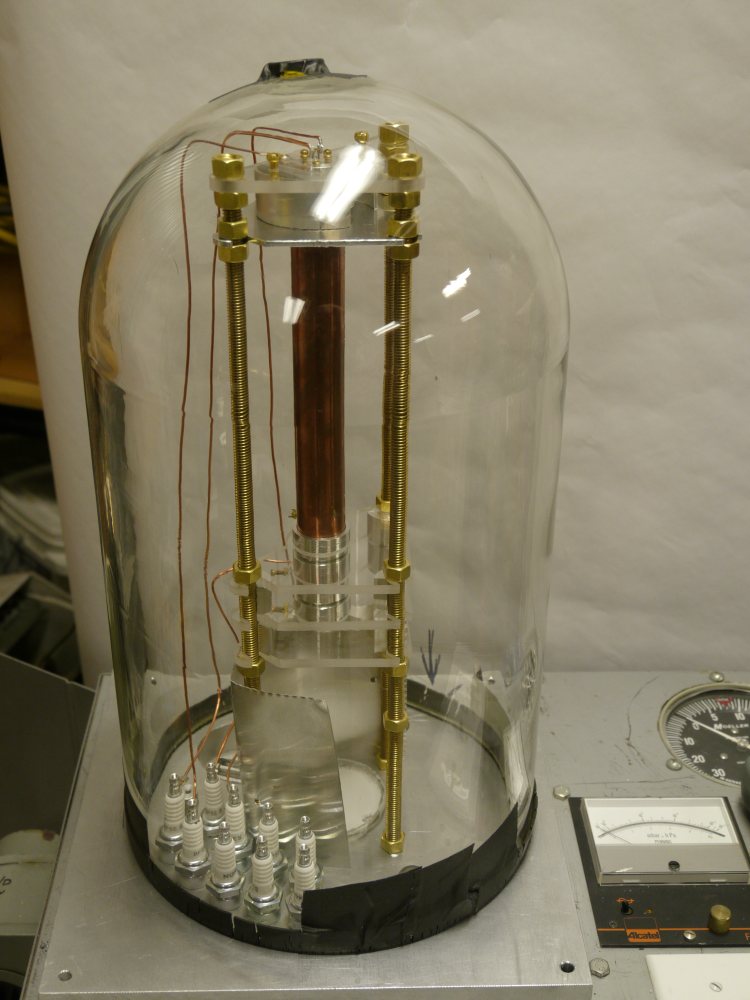
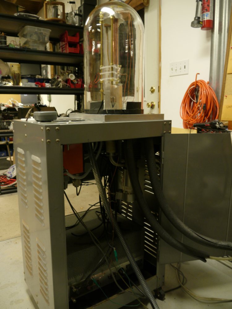
DIY Scanning Electron Microscope - Operation procedure
After getting back from Maker Faire (which is always a hugely enjoyable and inspiring event), I thought that my microscope might need some repairs. As it turned out, I only had to change the filament and tighten some screws that came loose during the trip back from the Faire. The microscope works just as well as it ever has -- I didn't even need to move my alignment magnets. I made this video to show everyone what using it is really like.
Also, if you haven't been able to attend Maker Faire yet, it really is as amazing and epic as you have heard. The intelligent and inspiring people who make it happen are a large part of the motivation that I had to build and display this microscope. In turn, I hope my project inspires others to create things and share their ideas with everyone. There's no better way to have fun and celebrate accomplishment at the same time!
Also, if you haven't been able to attend Maker Faire yet, it really is as amazing and epic as you have heard. The intelligent and inspiring people who make it happen are a large part of the motivation that I had to build and display this microscope. In turn, I hope my project inspires others to create things and share their ideas with everyone. There's no better way to have fun and celebrate accomplishment at the same time!
Monday, May 30, 2011
Product Review: Grizzly 4003G metal gunsmith lathe
I recently bought a Grizzly 4003G lathe, which has proven to be a very useful tool in my shop and a major upgrade from my previous lathe. The 4003G is a great value, and I would definitely recommend it for anyone looking for a 12x36 lathe for hobby or semi-pro work.
Friday, May 27, 2011
Shop lighting upgrade: T5 vs T8 fluorescent vs LED
I am in the process of upgrading the lighting in my shop. It currently has a number of 4-lamp and 2-lamp T12 4-foot fluorescent fixtures. The best solution is to replace the ballast in each of these fixtures with high-efficiency electronic ballast ($15), and replace the lamps with T8 high-CRI bulbs. This will save energy, and greatly improve the quality of the light. LEDs and T5 fluorescent are MUCH more expensive to install, and their energy savings are not nearly enough to justify the cost. Most LED systems actually use more energy than T5 or T8. Remember that running a T8 with an electronic ballast will provide more light than it's nominal rating, which is for magnetic ballasts. T5 are always rated for electronic ballasts, so it is not a fair comparison.
For new fixtures in my shop, the cheapest/best solution is to buy $10 "shop lights" and replace the ballast. The total fixture cost is $25, and efficiency is 96 lumens/watt for a total output of almost 6000 lumens. It can't be beat! Commercially-available T8 fixtures with electronic ballasts are more expensive, and the quality of the ballast is suspect.
For new fixtures in my shop, the cheapest/best solution is to buy $10 "shop lights" and replace the ballast. The total fixture cost is $25, and efficiency is 96 lumens/watt for a total output of almost 6000 lumens. It can't be beat! Commercially-available T8 fixtures with electronic ballasts are more expensive, and the quality of the ballast is suspect.
Wednesday, May 18, 2011
Interactive model of a 3D printer for teaching
I built a simple working model of a 3D printer for demonstration at a school. My intention is to show the students how 3D printers work at their most basic level. The model provides a hands-on activity and can create alphabetic letters or other small souvenirs that the kids can take with them.
Saturday, May 7, 2011
DIY Scanning Electron Microscope - Image Quality Improvements 3
A generous benefactor donated some proper SEM apertures to my project. These are much thinner than my brass plate in which I drilled a hole. This should increase resolution as there will be less scattering from the edges of my original, thick aperture plate


The main problem that I am having is that the oscilloscope X and Y amplifiers do not provide enough range or offset to easily control where the scan pattern hits the sample. I knew this would be a problem, so I included small mechanical X and Y stages for the specimen in the microscope. I even designed a vacuum-safe rotary passthrough into the vaccum chamber. The biggest problem is just connecting the rotary passthrough to the stage itself with a right-angle and/or flexible shaft arrangement. Space is very tight and the shaft must move with the stage, making for a difficult mechanical design.


The main problem that I am having is that the oscilloscope X and Y amplifiers do not provide enough range or offset to easily control where the scan pattern hits the sample. I knew this would be a problem, so I included small mechanical X and Y stages for the specimen in the microscope. I even designed a vacuum-safe rotary passthrough into the vaccum chamber. The biggest problem is just connecting the rotary passthrough to the stage itself with a right-angle and/or flexible shaft arrangement. Space is very tight and the shaft must move with the stage, making for a difficult mechanical design.
How to design a transistor circuit that controls low-power devices (tutorial)
I describe how to design a simple transistor circuit that will allow microcontrollers or other small signal sources to control low-power actuators such as solenoid valves, motors, etc.
Friday, May 6, 2011
DIY Scanning Electron Microscope - Image Quality Improvements 2
I've made some improvements to the microscope that have increased image quality somewhat. Here is a quick list of the changes:
-Made a new acrylic light guide that allows the scintillator to face the sample directly. The pipe is curved so that the light is directed upwards into the photomultiplier tube. The size of my bell jar necessitated that the PMT be mounted vertically, which is not good since a straight light pipe would cause the scintillator to be aimed directly at the bottom of the chamber.
-Added coaxial cabling and a fully-shielded box to the PMT amplifier circuitry.
-Adjusted PMT load resistor, and eventually installed a potentiometer so that I can change the load resistance to best match the raster scan rate
-Changed PMT amplifier circuitry so that the images are not inverted with respect to normal secondary electron micrographs
 This is a MEMs gyroscope. I pried off the cover to expose the die.
 This micrograph shows some structure on the die. Hopefully with better magnification and resolution, I'll be able to see the MEMs gyro itself.


 It appears to me that the blurriness in these images is somewhat constant across all magnifications. This leads me to believe that focus is not the main issue, and that the problem is with PMT signal recovery. Scanning at a slower rate should help this, but the PMT amplifier is AC-coupled, so the scan rate cannot get too low, and I also cannot see the image on the oscilloscope at low scan rates -- making focus and various other adjustments difficult. I also haven't found a good way to synchronize my camera shutter to the raster scan.
Monday, April 25, 2011
Piezoelectric Braille system with PC parallel port control and HV transistors
Here's a project that makes use of these electronic Braille characters: http://www.metec-ag.de/braille%20cell%20p16.html
I built a bunch of transistor amplifiers and use two 74hc373 chips driven by the parallel port to control the state of both Braille characters.
Excellent resource for PC parallel port control:
http://www.beyondlogic.org/spp/parallel.htm
I built a bunch of transistor amplifiers and use two 74hc373 chips driven by the parallel port to control the state of both Braille characters.
Excellent resource for PC parallel port control:
http://www.beyondlogic.org/spp/parallel.htm
Thursday, April 14, 2011
Fiberoptic mouse with quadrature encoders and custom shutter buttons
Here's another project similar the the fiberoptic joystick that I built. It uses the same 62.5 micron telecom fiber to sense X/Y velocity as well as two buttons in a standard computer mouse. This mouse is designed to be used in environments were electrical signals cannot be tolerated.
Tuesday, April 12, 2011
My Tektronix contest entry
Vote for me here: http://mytektronixscope.com/videos/
I am using my Tektronix 2246 analog oscilloscope to show the image generated by my DIY electron microscope. The 2246 is operating in X-Y mode, with the channels connected to a raster scan generator. The vertical scanning frequency is about 30Hz and the horizontal frequency is about 10KHz. The trace brightness (Z axis) is modulated with the secondary electron signal from the microscope.
I am using my Tektronix 2246 analog oscilloscope to show the image generated by my DIY electron microscope. The 2246 is operating in X-Y mode, with the channels connected to a raster scan generator. The vertical scanning frequency is about 30Hz and the horizontal frequency is about 10KHz. The trace brightness (Z axis) is modulated with the secondary electron signal from the microscope.
Sunday, April 3, 2011
DIY Scanning Electron Microscope - Image Quality Improvements 1
This weekend, I spent some time making incremental improvements to the image quality of my scanning electron microscope. I decided to abandon my own X/Y deflection amplifier in favor of the amplifier from a commercial analog oscilloscope. The oscilloscope's amplifier is extremely linear, easy to control with the front panel knobs, very fast, and has a "good enough" amount of deflection and offset, but it could be better. I will try to compensate for this by adjusting the deflection plate length and separation distance.

 Here is a shot of the aluminum window screen that I have been using as a test target. The wires in the target are pretty straight, indicating that the system is relatively linear, and can produce an undistorted image.

 This photo shows an integrated circuit -- this one is a MEMs gyroscope. The wild black/white pattern on the hard-edged object at lower right is the actual silicon die. I imagine the strange pattern is caused by the varying conductivity of the die's surface. The die's bond wires can be seen clearly as well as the metal pads that connect the bond wires to the chip's external leads.
I spent a good part of the day redesigning my filament power supply. It is now DC and fully regulated. The original design was AC, which caused huge focus problems (the beam would fluctuate at 60Hz, so I rectified it to unregulated DC. Later, I found that the ripple in the output voltage was also causing image problems. Since my image scan rate is on the order of 30Hz (in vertical), I would see the problems caused by 60Hz noise as rolling bars in the output image. The ripple in the DC filament voltage caused strange black bands to roll down the video image. I suspect this happened because of slight changes in the electron gun's bias. I am really surprised that the 2V filament voltage would have any effect on the bias voltage of hundreds of volts, but it apparently does.
 The next problem I found was apparent at higher magnifications. This photo shows a close-up of one of the chip's bond wire pads. The pad in reality is very straight, but it is quite curvy in this image. At first, I thought this problem was caused by a ground loop between the X/Y amplifier and the rest of the microscope's power supplies. No, it turned out to be caused by the oscillating magnetic field created by the diffusion pump's cooling fan and the pump's heater.
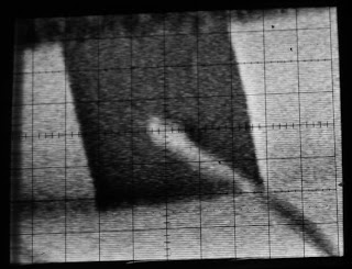
I switched off the pump and fan, and the problem went away. I thought about adding magnetic shielding to the chamber, but I think I will just accept with the wavy image while focusing/panning, then turn off the pump to record an image.
My SEM design is ideal for teaching and exploring electron beam control, but has several major design flaws, which I will summarize for those interested in creating homebrew SEMs with actual utility value:
1. The photomultiplier tube is extremely sensitive to ambient light. In my SEM, I use a black plastic light-tight box to cover the glass bell jar and keep it protected from room lighting. However, the SEM's own filament produces enough light that escapes through the electron gun's vent holes to cause big problems. I can only run the photomultiplier tube at about 700V, before exceeding the average maximum rated anode current (.1mA). The SEM imaging system is AC coupled so the offset is not a deal-breaker, but I believe the DC offset also creates a lot of AC noise in the output image, and would also damage the photomultiplier if I should run it for a long time or greatly exceed the max average anode current. The solution is to build the microscope column from an opaque material (metal), and arrange the electron gun such that there is no optical path from its vent holes to the specimen chamber of the SEM (like all commercial designs).
2. Remove magnetic disturbances or build the SEM column from a magnetically-shielding material.
3. Use very clean, tightly regulated DC for all supplies involved with the project. This is a sensitive analog system, and it picks up every kind of noise.
4. The main accelerating voltage need not be very high (eg 3KV works fine). Lower-energy electrons are easier to deflect and focus, lowering the requirements for those respective power supplies. So far, I haven't seen any benefit to using higher accelerating voltages.
5. Minimize the use of all insulators inside the chamber. Try to build structures that stand on their own without insulator support, or shadow insulators from the electron beam with conductive surfaces. I will talk about this more in a future video, but it caused me many problems in the early weeks of the electron column design.
My next actions will target the overall softness of the image. A youtube commenter pointed out that my aperture disc is much too thick (.010" thick, with a 100um hole). In the pinhole photography world, this would be considered a silly setup and would lead to soft images. I am inclined to believe a similar thing is happening with the electron beam, and will try the same aperture size with a thinner sheet.
I will also try to reduce the amount of light coming out of the electron gun and/or reduce the amount of light entering the photomultiplier. This should reduce the grainy high-frequency noise in the image.
PS, I also think that all of my images are inverted with respect to the normal secondary-electron images from SEMs. All of the images that I have posted so far have dark regions where secondary emission was high. I will probably correct this by adding another inverting opamp the signal chain.

 Here is a shot of the aluminum window screen that I have been using as a test target. The wires in the target are pretty straight, indicating that the system is relatively linear, and can produce an undistorted image.
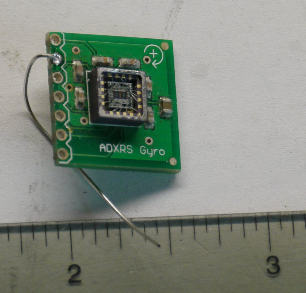
 This photo shows an integrated circuit -- this one is a MEMs gyroscope. The wild black/white pattern on the hard-edged object at lower right is the actual silicon die. I imagine the strange pattern is caused by the varying conductivity of the die's surface. The die's bond wires can be seen clearly as well as the metal pads that connect the bond wires to the chip's external leads.
I spent a good part of the day redesigning my filament power supply. It is now DC and fully regulated. The original design was AC, which caused huge focus problems (the beam would fluctuate at 60Hz, so I rectified it to unregulated DC. Later, I found that the ripple in the output voltage was also causing image problems. Since my image scan rate is on the order of 30Hz (in vertical), I would see the problems caused by 60Hz noise as rolling bars in the output image. The ripple in the DC filament voltage caused strange black bands to roll down the video image. I suspect this happened because of slight changes in the electron gun's bias. I am really surprised that the 2V filament voltage would have any effect on the bias voltage of hundreds of volts, but it apparently does.
 The next problem I found was apparent at higher magnifications. This photo shows a close-up of one of the chip's bond wire pads. The pad in reality is very straight, but it is quite curvy in this image. At first, I thought this problem was caused by a ground loop between the X/Y amplifier and the rest of the microscope's power supplies. No, it turned out to be caused by the oscillating magnetic field created by the diffusion pump's cooling fan and the pump's heater.
I switched off the pump and fan, and the problem went away. I thought about adding magnetic shielding to the chamber, but I think I will just accept with the wavy image while focusing/panning, then turn off the pump to record an image.
My SEM design is ideal for teaching and exploring electron beam control, but has several major design flaws, which I will summarize for those interested in creating homebrew SEMs with actual utility value:
1. The photomultiplier tube is extremely sensitive to ambient light. In my SEM, I use a black plastic light-tight box to cover the glass bell jar and keep it protected from room lighting. However, the SEM's own filament produces enough light that escapes through the electron gun's vent holes to cause big problems. I can only run the photomultiplier tube at about 700V, before exceeding the average maximum rated anode current (.1mA). The SEM imaging system is AC coupled so the offset is not a deal-breaker, but I believe the DC offset also creates a lot of AC noise in the output image, and would also damage the photomultiplier if I should run it for a long time or greatly exceed the max average anode current. The solution is to build the microscope column from an opaque material (metal), and arrange the electron gun such that there is no optical path from its vent holes to the specimen chamber of the SEM (like all commercial designs).
2. Remove magnetic disturbances or build the SEM column from a magnetically-shielding material.
3. Use very clean, tightly regulated DC for all supplies involved with the project. This is a sensitive analog system, and it picks up every kind of noise.
4. The main accelerating voltage need not be very high (eg 3KV works fine). Lower-energy electrons are easier to deflect and focus, lowering the requirements for those respective power supplies. So far, I haven't seen any benefit to using higher accelerating voltages.
5. Minimize the use of all insulators inside the chamber. Try to build structures that stand on their own without insulator support, or shadow insulators from the electron beam with conductive surfaces. I will talk about this more in a future video, but it caused me many problems in the early weeks of the electron column design.
My next actions will target the overall softness of the image. A youtube commenter pointed out that my aperture disc is much too thick (.010" thick, with a 100um hole). In the pinhole photography world, this would be considered a silly setup and would lead to soft images. I am inclined to believe a similar thing is happening with the electron beam, and will try the same aperture size with a thinner sheet.
I will also try to reduce the amount of light coming out of the electron gun and/or reduce the amount of light entering the photomultiplier. This should reduce the grainy high-frequency noise in the image.
PS, I also think that all of my images are inverted with respect to the normal secondary-electron images from SEMs. All of the images that I have posted so far have dark regions where secondary emission was high. I will probably correct this by adding another inverting opamp the signal chain.
Saturday, March 26, 2011
DIY Scanning Electron Microscope - Sources, Costs and References
Metal aluminum window screen
 Just a few linearity problems ;)

 I used an oscilloscope's X and Y amplifiers for these images. It has much better linearity than my own, but not enough differential voltage or offset range.
The sum total of the big-ticket items shown in the video is $1485. This does not include hoses, wiring, raw metal, teflon, screws, a cabinet, etc. It also does not include an oscilloscope, which can be a very simple model (under $100 on eBay) as long as it has a z axis (brightness) input. Your diffusion pump or diffusion pump baffle may also require a water chiller.
Here are a list of information sources that helped me with this project:
Teralab - Homebuilt electron gun and other great projects
http://www.teralab.co.uk/Experiments/Electron_Optics/Electron_Optics_Page1.htm
Popular Mechanics video on commercial desktop SEM
http://www.popularmechanics.com/technology/gadgets/4218957
Hamamatsu - Supplier of PMTs
http://sales.hamamatsu.com/assets/applications/ETD/pmt_handbook_complete.pdf
TV to oscilloscope circuit
http://www.electronixandmore.com/project/14.html
CRT oscilloscope clock circuit
http://web.jfet.org/vclk/
Charged particle optics simulation program
http://www.electronoptics.com/
"A Simple Scanning Electron Microscope" P.J. Spreadbury -- Advances in Imaging and Electron Physics Vol 133 Chapter 2.5 (no link).
ISI SEM refurb at home
http://members.tm.net/lapointe2/Scanning_Electron_Microscope.html
Great technical info on cathodes and wehnelt cup spacing. Most of the article concerns LaB6 cathodes, but there is a short paragraph on tungsten cathodes.
https://www.kimballphysics.com/cathode/support_PDF/Cathode_ES423_LaB6_info.pdf
Numerous websites that gave background and operational information about SEMs.
Lots of web searches
Nearly all raw materials for this project were purchased from McMaster-Carr. All power supplies were purchased on eBay, or I already had them, in which case they came from a surplus store or flea market. Nearly all of the electronic components came from Jameco.
Monday, March 21, 2011
DIY scanning electron microscope - Overview video

Today, I finally produced an image with my DIY scanning electron microscope. I've spent the last few months working on this project, and am encouraged by today's success. There is still a lot of work left to do in making the image higher resolution, and eliminating sources of noise, however this image proves that all parts of the microscope are operating as designed.
Monday, February 28, 2011


555 Timer Contest Entry
This blog post will show my entry for the 555 timer circuit design contest at http://www.555contest.com
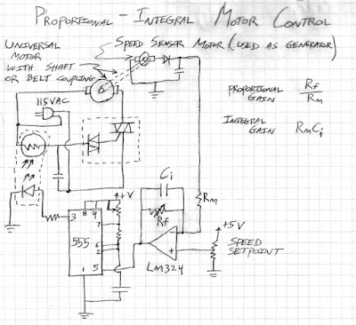
This is a motor speed control circuit that allows safe and easy control of 115VAC "universal motors" like drill motors, blender motors, other power tools, etc.
The motor is controlled directly by a triac-diac component that is found in variable-speed universal motor devices (such as electric drills.) The component will not allow current to flow through the motor until the R-C network charges to a certain level. In this case the capacitance is fixed, but the resistance is determined by a CdS photoresistor. A standard LED is optically coupled to the CdS photoresistor, and the LED is controlled by a 555 astable circuit. The duty cycle of the 555 output waveform will determine the average amount of light falling on the CdS photoresistor, and thus the CdS resistance, and thus the current flowing through the motor. For best operation, the 555 output frequency should be much higher than the mains AC frequency (ie 60 Hz). A good value for the 555 frequency would be about 5 KHz.
The 555 control voltage is set by an opamp circuit (LM324) that amplifies the difference between a user-set voltage and a voltage generated by a small motor whose shaft is coupled to the main motor being controlled. The small motor's function is to generate a DC voltage that is proportional to shaft speed. Its value is amplified and integrated by the opamp circuit for programmatic proportional and integral control.
The 555 serves as a high-current pulse driver for the LED, taking an analog control signal and allowing some control of the pulse rate and height via the R-C timing network and current-limiting resistor.
Thursday, February 17, 2011
How to build an air muscle and use it in a force-feedback joystick
In this video, I describe how to build an air muscle, and use it to create a force-feedback joystick
Link to the instructables article (not written by me): http://www.instructables.com/id/How-to-make-air-muscles!/
Silicone tubing - McMaster 51135K281
Braided wire loom (polyester) - McMaster 9284K413
Link to the instructables article (not written by me): http://www.instructables.com/id/How-to-make-air-muscles!/
Silicone tubing - McMaster 51135K281
Braided wire loom (polyester) - McMaster 9284K413
Thursday, January 27, 2011
Cathode ray tube disassembly and explanation
I cut open a cathode ray tube (picture tube, or CRT) and explain the internal parts and their function.
Subscribe to:
Posts (Atom)